



Your best friends here are a hands-free method of holding the circuit board, along with disposable vinyl gloves and a head-mounted magnifier with an LED illuminator. Begin assembly by placing the dry board atop a clean saucer with the copper pads facing up. Keep it in place with a bit of masking tape.
2a. Capacitor
Next, solder C1 to the board. Be sure to hold the tiny capacitor with tweezers and do not touch it or the surface of the board with your bare fingers. Apply a thin layer of solder to one of the two pads for C1. Then carefully place the two ends of C1 over its two pads and secure it in place with tweezers or masking tape. Carefully touch the soldering iron to the junction of the chip and the solder-covered pad. The capacitor should remain in place. Touch a solder wire to the junction of the second pad and the circuit board. The solder should flow around this end of C1 and secure it to the board.
For more tips on surface-mount soldering, see the last step of this article.
2b. Amplifier chip
The gain of the ADA4530 is so high that the chip is extremely sensitive to anything touching pin 8, the input pin to which the signal from the LED used as a photodiode will be connected. Therefore, pin 8 must be very carefully bent, from straight down to straight away from the chip, before its remaining seven pins are soldered to the board.
Bending pin 8 requires considerable care to avoid dropping the expensive chip, which might bounce off the paper towel and disappear on the floor. My approach is to hold the ADA4530 with the narrow jaws of clean needlenose pliers and use clean SMD tweezers to carefully bend pin 8 outward so it is perpendicular to the chip. (Be sure to wipe the pliers and tweezers with isopropyl alcohol before using them.) I have used this method for a dozen or more ADA4530 SMD chips, and none were dropped. If you have any spare SMD ICs, practice this procedure before doing so with the expensive ADA4530.
Set the ADA4530 on a clean paper towel. On the circuit board, carefully place a thin layer of solder over the pads for pins 1 and 5 of the ADA4530. Remove excess solder with solder wick. While wearing disposable vinyl gloves, secure the chip to the board with a bit of masking tape across pins 3, 4, 5, and 6. Then very carefully touch your soldering iron to where pin 1 of the IC touches its solder-coated pad. If the ADA4530 is properly aligned, carefully remove the tape and solder pin 5 to the board. Complete the installation of the ADA4530 by touching the remaining pins with the iron and solder wire. Use your magnifier to be sure all seven pins are properly soldered.
2c. Mini connector
Next, insert the four pins of a 4-conductor mini connector socket into their holes on the top side of the board and then solder them in place on the back side.
2d. LED
Cut a square of vinyl tape or Velcro-style hook-and-loop tape and apply it to the back side of the board where the LED will be installed. This insulates the LED from the board. Be sure to leave the holes through the board open.
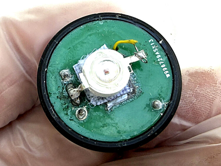
A 620nm red LED is soldered to the back side of the board. I have used both wire-lead and surface-mounted LEDs with extended, flat terminals, the latter of which I prefer. The positive pin, marked with a “+” sign, is soldered between the two center pins of the mini connector on the back side of the board.
While still wearing vinyl gloves, add solder between the two center pins of the connector. Then press the LED’s anode terminal against the two connector pins and heat with your soldering iron until the terminal is melted into the solder between them.
Carefully remove the insulation from both ends of a 1″ length of thin hookup wire and solder one end to the LED’s cathode terminal. (Bend the terminal slightly upward if it is touching the board.) Insert the other end of the wire through the pass-through hole in the board. It will be connected later. This shows the back side of the board with the LED soldered in place.
2e. Feedback resistor and capacitor
It is essential to wear vinyl gloves for the next step to avoid touching RF, a 5GΩ or 10GΩ resistor, and CF with bare fingers.
First, carefully solder the leads of CF, a 10pF or 20pF capacitor, across the leads of RF. The capacitor should be just below the resistor but not touching it. Clip off CF’s excess leads.
Soak the combined RF + CF for several minutes in a clean water bottle cap filled with isopropyl alcohol to remove all impurities. Agitate RF and CF within the alcohol before removing them. Then hold RF and CF with clean tweezers and blow the alcohol away with a duster.
Very carefully insert one lead from RF through the hole between the pads for C1 and CF and solder the lead in place.
Bend the second lead from RF + CF across the board and solder it to the thin wire from the LED that you inserted from the back side. The board is completed by carefully soldering a short length of insulated wrapping wire between this junction and the unconnected pin 8 of the ADA4530.


These photos show the board’s top, bare and assembled. The large orange component is RF, a 5GΩ feedback resistor (use 10GΩ for more sensitivity). The round object below it is the feedback capacitor CF soldered to the leads of RF. These components and the board itself should be touched only when you are wearing disposable vinyl gloves.
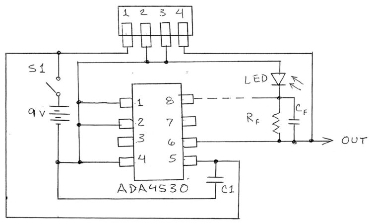
The circuit diagram shows how the various connections are made between the circuit board, 4-pin plug and socket, the power switch, the 9V battery, and the Onset 16-bit data logger. After the external connections have been made, dip the entire assembled board into a small container filled with isopropyl alcohol and gently shake the board for 30 seconds or so. This will remove dust and other contaminants that will greatly reduce the circuit’s sensitivity. Remove the board and spray away the alcohol with a burst from a duster, and install the board into the end of the lens tube.
